TM 9-215 THOMPSON SUBMACHINE GUN, CAL. .45, M1 Section V. DISASSEMBLY AND ASSEMBLY
a. Magazine.
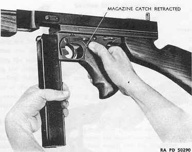
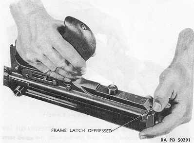
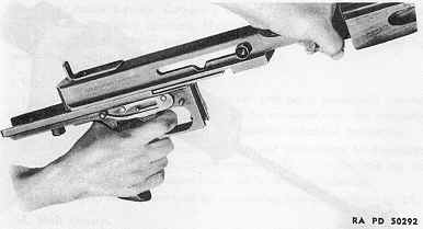
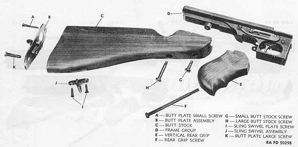
b. Sling. Disconnect the sling hooks from the link and swivels and remove the sling. c. Butt Stock Group. Unscrew the two butt stock screws and remove the stock. It is not necessary to remove butt stock group to remove frame. d. Frame Group.
e. Bolt and Recoil Spring Group.
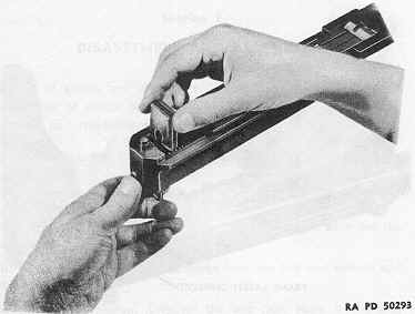
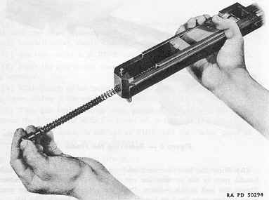
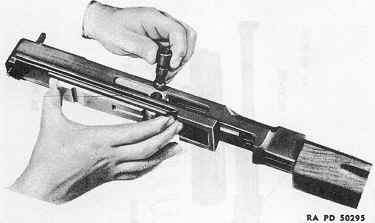
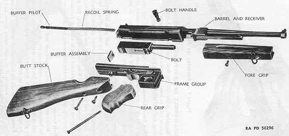
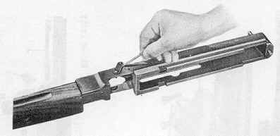
(1) Support muzzle of barrel on knee or table with open side of receiver facing the operator. (2) Press the buffer pivot slightly into the receiver and withdraw the buffer (fig. 7). Do not release the pressure on the pilot. Gradually pull out the pilot with recoil spring (fig. 8). (3) Slide the bolt rearward and tip the rear end until the bolt handle rests in the semicircular cut on the right side of the receiver. Steady the bolt in this position. Press the bottom of the hammer rear- ward to disengage the bolt handle and remove the handle (fig. 9). f. Disassembled view of gun shown in figure 10.
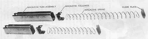
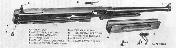
19. DISASSEMBLY OF GROUPS AND ASSEMBLIES. a. Magazine. Slide out the floor plate, holding fingers over bottom of magazine tube to keep magazine spring from flying out. Withdraw the spring and the follower (fig. 11). b. Butt Stock Group. Complete disassembly of butt stock is not necessary for ordinary cleaning. However, when necessary for replacement of broken or worn parts, butt stock plate may be removed by removal of screws holding it in place (fig. 12). c. Barrel and Receiver Group.
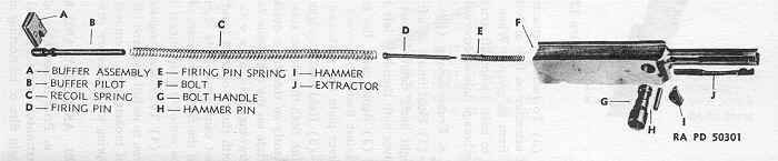
d. Bolt Group.
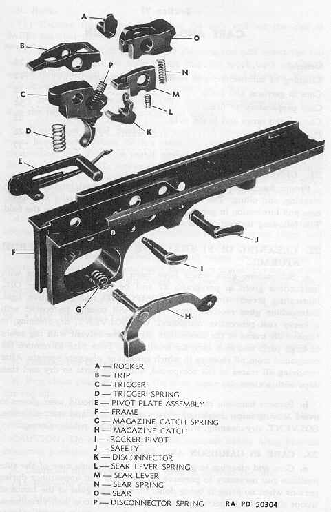
e. Frame Group (figs. 16, 17 and 18).
20. ASSEMBLY AND REPLACEMENT. a. Prior to assembly, all parts must be free of dirt, rust, and other extraneous matter. Metal parts in contact must be covered with a light film of lubricating oil. In general, assembly and replacement are in reverse order of disassembly and removal. However, the following precautions should be observed in order that the parts will function properly after the gun is assembled. b. In assembling trigger mechanism, first see that the magazine catch is in place. Assemble springs- in their proper recesses. Assemble disconnector to trigger by depressing disconnector spring and sliding disconnector into place.
c. If extractor has been removed, slide it into place, lifting head only enough to clear stud; avoid excessive pressure. Insert firing pin and spring in bolt, being careful to avoid stretching the firing pin spring. Place hammer in position with rounded edge upward and push hammer pin into place. d. Place bolt in receiver, slide it forward and tilt the rear until the semicircular cut on the right side of the receiver is aligned with the hole for the bolt handle on the bolt. Steady the bolt in this position. Rotate the hammer and insert the bolt handle, making sure that the handle is firmly secured. e. Slide bolt to the rear and hold it firmly with one hand. With other hand start pilot and spring through hole in rear of receiver and push them into recess in bolt until the pilot enters the recess in bolt. Gradually release the bolt and at the same time push the pilot forward until the groove on the pilot is inside the receiver. Replace the buffer in the groove on the pilot.
f. Before fitting frame to receiver, be sure that safety is set at FIRE position and rocker pivot at FULL AUTO. Slide frame onto receiver and at the same time squeeze trigger. Frame latch will lock frame in position. Holding trigger depressed, operate bolt handle back and forth several times to test mechanism.
|